The importance of Automotive Ethernet Switch & Network testing for Connected Autonomous Vehicles
It is now commonly accepted that Ethernet is the new de facto standard for in-vehicle communication and certainly in Connected Autonomous Vehicles. Also, new Electric Vehicle OEMs are relying heavily on Ethernet for in-vehicle communication backbones as they are in the privileged position of designing and engineering their vehicles from scratch. The immense amount of data generated by sensors, cameras, radars, lidars and external data flows like V2x, Telematics and Infotainment simply cannot be transported on classical automotive communication systems. There are powerful incentives for improving existing technologies like CAN (1Mbit/s) to CanXL (10Mbit/s), but the advantage of having most of the vehicle communication based on the same technology (Ethernet) is clearly driving the growth of Automotive Ethernet.
It is also commonly understood that the traditional technologies will have to coexist with Automotive Ethernet for some time, especially for data rates below 10Mbit/s. This will further drive the need for communication gateways between Ethernet and other technologies.
So the situation we have looks like this. Ethernet is a well-known communication technology from the telecommunication and information technology industry. It is also used in various other industries like industrial automation. It is mainly standardized in the IEEE Organization and follows the OSI layer model of communication. For Automotive applications, various other organizations are involved such as the OPEN Alliance. Currently most of the technology standardizations from the Automotive industry like the OPEN Alliance will be integrated into IEEE standards and test specifications will be integrated into ISO standards.
Traditional Ethernet uses different types of physical transmission lines like twisted pair copper cable in an unshielded and shielded variant with 4 to 8 wires. But it can also be used on fiber cable, coax cable or even in a wireless RF variant. In the past, Ethernet was mainly a BUS architecture like CAN or LIN, and we see new variants of Ethernet like 10Base-T1S/L which is again using the BUS architecture. Today, most of the Ethernet architecture is based on the switching architecture. The main difference between Ethernet and Automotive Ethernet is the physical layer as Automotive Ethernet only uses a 2-wire unshielded twisted pair cable which is like the cable used for CAN. This reduces the weight of the Ethernet cabling which improves the assembly process significantly.
The core problem with Ethernet in systems like in-vehicle networks where safety is a top priority is that most applications offer better ways of prioritizing data frames in the setup. Standard Ethernet networks use the “best effort” principle, which means the network components forward a data frame from A-to-B on their “best effort”. Within in-vehicle networks we must make sure that data frames relevant to safety are handled with the highest priority, the smallest delay, and maximum reliability. Different network transport protocols are used to enable these features, and the most famous of these is the “Time Sensitive Networking” protocol suite.
In this article however, we want to focus on the most fundamental devices in any well-performing Ethernet network: the Ethernet switches!
Modern Ethernet networks use switches as the core backbone elements, which makes them the most important components in any robust system. Switches usually operate at the OSI layer 2, the data link layer, and can be found in hundreds of different configurations based on the number of ports, different port speeds and supported data link layer protocols. Also, the network architecture with switches allows multiple variants of how a switch behaves and performs in a network.
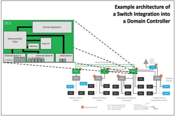
There are multiple challenges in the process of designing, engineering, and setting up an Ethernet network. Here is an example of an in-vehicle network with an Ethernet backbone (Figure 1):
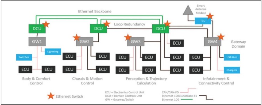
The network includes different switch configurations and switches are part of different device types in this setup. They are part of Domain Controller, Gateways, and a Telematics Control Unit. We can also see that the switches have different amounts of ports, different speeds, and also that they are part of different network architectures. What we cannot easily see in this graphic is which kind of Layer 2 protocols they are using. We assume that in this setup we only use standard Layer 2 protocols like ARP, MAC, STP and VLAN. Based on this assumption, it is fine to ask the fundamental question: “what switches do I have to use from which vendor and how do I test them?”
Before we dive into the details of testing, let’s answer the basic question of why “switch testing” is important to ensure a well performing in-vehicle network. As mentioned earlier, switches are the backbone of an Ethernet network, and due to the architecture of Ethernet networks, one non-performing switch out of dozens in the network could cause a major communications failure. While not every application message on the network will go through every switch in the network, a misconfigured or poorly chosen switch can create a flood of unnecessary traffic across the entire network, possibly impacting the “good” communication messages. This kind of “bad” traffic is called a “broadcast storm”. In modern in-vehicle networks we will find multiple ECUs from different vendors, with multiple switches also from different vendors. The interoperability of these switches and the common usage of the same configuration parameters are essential to get an Ethernet network up and running. We need to acknowledge that the switch functionalities are as important as the different functions of an ECU or the connected end-devices. Switch & network testing is the functional testing of the communication backbone additionally to the functional testing of the core vehicle applications.
Now let’s focus on the most important factors when selecting and validating switches for in-vehicle networking:
- Performance & Interoperability: non-blocking architecture, average delay, average jitter, and start-up time. Most of them (and even more) are available in pre-defined test suites like RFC-2889 and RFC-2544.
- Security & Robustness: VLAN separation, broadcast storms, redundancy
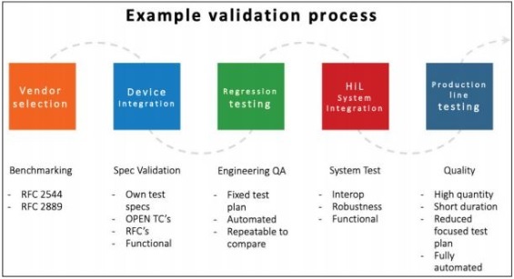
There is also a clear proposal for how to integrate testing in different development stages and production start-up phases (Figure 2):
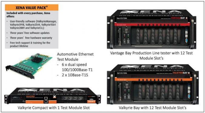
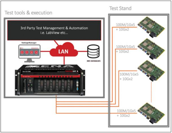
Which kind of test tools are required for switch & network testing? As we are talking about test & validation which needs to be reliable and reproducible, a traditional “software-only” solution is not recommended as the additional hardware required could be different for the test engineers involved, and the performance of the hardware is not predictable for the test software being used. Also, a switch or network test usually requires multiple test ports to perform the needed test cases. The required test tool should therefore combine dedicated soft- & hardware where the test management and analysis are done with the software and the test execution is done by the hardware (and embedded software). The test tool should also natively support the different kinds of interfaces, related to speed and physical layer, to avoid using additional components like media converters or adapters which potentially could influence the test results. Example test tools are shown in Figure 3.
Now, let’s look at the different characteristics and potential additional requirements of the five stages of testing listed in Figure 2 above.
VENDOR SELECTION:
Vendor selection is a process that should achieve two goals:
- Validate that a vendor can meet the minimum performance metrics
- Let you compare how one vendor performs against another
The test requirements and test cases required for these two goals are very general, and the focus is to rely on reproducible test results during the validation of different switch configurations and different vendors. Every test should be 100% the same as the one before. To make these tests as transparent as possible, it is recommended to use pre-defined test suites like the RFC-2889 “Benchmarking Methodology for LAN Switching Devices” and the RFC-2544 “Benchmarking Methodology for Network Interconnect Devices”. Another reference could be the Y.1564 “Ethernet service activation test methodology”.
These collections of test scenarios can be adjusted and customized to the specific use case and can be re-used for multiple tests during a validation cycle. Using these test suites will guarantee reproducible and reliable test results.
DEVICE INTEGRATION:
What is “Device Integration”? Research, development, and engineering use different terms for product development stages so let’s define the stage after selecting a key component such as a switch as the “integration of this key component into a device” like an ECU (Electronic Controller Unit) or DCU (Domain Controller Unit) shown in Figure 4. Another description of this stage could be the stage of “Sample A” i.e., a prototype with limited functionalities.
The purpose of device integration testing is to test the switch device against its own test specifications and repeat the testing against generally available test plans like the RFCs mentioned above.
Industry-specific test specification are usually integrated into this phase of testing. An example of a broadly used test specification in the automotive sector is the OPEN Alliance TC11 test specification. It includes test cases from the RFCs as well as adjustments and additional test cases that meet specific needs of in-vehicle networking devices.
REGRESSION TESTING:
Once a device moves into a more general and broader development stage, continuous regression testing is needed in parallel with the engineering process. At dedicated milestones a pre-defined test plan will be executed, and the engineering milestone will be validated.
The main purpose is to identify any effects of the implementations on the key functionality of the ethernet switch. The test plans for regression testing are possibly different for each engineering task, but it is important that these test plans are not changed during this stage to avoid non-comparable test results, and the risk of potential bugs not being identified.
Regression testing is usually fully automated for the engineer – ideally there should only be a “start” button and a “pass/fail” result. If a test fails, a detailed report should be generated by the test tool.
From the Automotive perspective we would describe this engineering stage as “Sample B”: fully integrated hardware with partially integrated software or software under development. At this stage, the Ethernet switch functionalities are usually already fully integrated as a hardware-only part, but with some configuration options. As the overall development of the software and its configuration can still influence the performance and functionality of the switch device, switch regression testing is mandatory in this stage.
HIL SYSTEM INTEGRATION:
The following development and testing stages are for the system integration and hardware in-the-loop testing. This is where the single device will be integrated into the physically available or partially simulated full system, like the Ethernet backbone, the ADAS-Domain, Infotainment-Domain or even the whole vehicle’s electronics. The related Automotive development stage can be described as “Sample C/D” fully functional hardware and software or production grade.
The main purpose of the HiL testing is to validate the system functionality. But why do we need to test the switch or even the network functionality once again?
During the “vendor selection” stage we already validated the interoperability of the switch integrated in the device under development. However, within the whole system there is a high possibility that some ECUs are from third-party vendors, and we cannot guarantee that these devices are fully compliant with the general switch and networking specifications.
Also, the behavior of single device integrated into a network can be different compared to a standalone test of the switch functionalities.
It is critical for the main HiL test process to ensure a 100% working and performing communication infrastructure made up of the switches and the network built with those switches. If this isn’t done, the troubleshooting will be much more difficult as it will be necessary to find out if the failure was caused by an application error or a network communication error. The most efficient way is to validate the communication layer first so you can exclude the network in any subsequent troubleshooting.
The required test plans include a subset of the test cases executed in earlier stages, together with some new test scenarios. These are mainly related to core switch and network performance metrics, like end-to-end performance (simulation of the Ethernet end devices), network impairments (jitter, delay, and packet loss) to validate redundancy and robustness and Quality of Service (QoS) testing to validate the overall network functionality.
PRODUCTION LINE TESTING:
The final stage in the development and test process is the start of production (SoP) which usually also includes a set of devices bring up tests. As key functions are validated in this process some of the Ethernet functions need to be validated as well. After providing the soft- and firmware, the device must be tested to verify that the switch is configured correctly, and if the hardware specifications match with the requirements. Typical test scenarios are interface speed check, internal loopback packet loss test, Ethernet switching performance check and basic Quality of Service analysis.
The key characteristics of the test station and setup are: High quantity of simultaneous device testing with a quick turn around time. The tests need to be fully automated with simple pass/fail criteria and integration into the quality documentation process.
An Example of a Production line test setup is shown in Figure 5.
Conclusion:
The most important take away should be that Ethernet as the “new” network communication technology implements a second layer of key functionalities to the devices and the system. The “Network” is no longer just a wire, like with CAN. Instead, the network is a set of switches (or other active network components like routers) plus the wires.
This also means that these components should be tested as separate functional components. We should not assume that if we can validate the ECU functionalities as “Pass” that the switch in the ECU will also have a “Pass” if it is connected to the system network, as we potentially now have all communication traffic going through this switch (ECU) and not only the messages belonging to this device.
Switch and network testing must be an integrated test procedure in all development stages to ensure the expected network communication quality.
Author:

Thomas Schulze
Senior VP Sales & Marketing
Xena Networks
Thomas is responsible for Xena’s global sales & marketing activities, and business development of Xena’s Automotive Ethernet and Time Sensitive Networking (TSN) products. With over 15 years of professional experience in telecom & IT testing, his credentials are impeccable. He combines in-depth technical understanding with an impressive track record in sales and business development working with leading providers of test & measurement solutions for Ethernet, cellular and positioning networks.
Published in Telematics Wire