
The move to advanced driver-assistance systems (ADAS), the connected cars requires reliable in-vehicle networking and high-bandwidth connections. Cars can now contain complex embedded electronics connected to high-speed sensors located around the car through multiple yards of cable harnesses. Traditional automotive networks such as CAN, CAN-FD, LIN, and FlexRay simply don’t provide the necessary bandwidth to support all of the devices and applications found in modern cars. We have new high-speed Automotive network standards adopted in car beyond 10Mbps like Automotive Ethernet.
Reliability is the most important aspect of Automotive design as some of the Electronics components are used for safety purpose. Electronics system in the case need to be tested across the entire design cycle of car. Also, just stand-alone component test is not enough. System level signal integrity test is very important to meet Reliability criteria.
In-Vehicle Network plays very critical role here as it need to reliably transfer data from one node to other at harsh automotive environment (Noise, High Temperature and vibration). User need to perform Signal Integrity test at System level, scenario test like system performance test in presence of Electromagnetic or Gaussian noise, Protocol test etc. In this article we will learn about performing system level Signal Integrity test for High speed In-Vehicle Network standards like Automotive Ethernet.
Automotive Ethernet
The need for greater performance and integration across vehicle subsystems is driving an industry wide move to Automotive Ethernet. Although the automotive standard has its origins in Ethernet, it incorporates significant changes at the physical layer to meet automotive requirements. The first version of the standard was known as BroadR-Reach and is being supplanted by the IEEE versions known as 100BASE-T1 (802.3bw) and 1000BASE-T1 (802.3bp).
The standard being designed into most cars today is 100BASE-T1, which supports 100 Mbps operation in the very noisy automotive environment. This data rate is significantly faster than traditional bus systems such as the CAN bus. Future designs will use 1000BASE-T1, at 10X the data rate. As signaling moves to higher data rates, so too does the need for comprehensive design validation at the system level to ensure interoperability and reliable operation across the many ECUs and sensors; design considerations that were safely overlooked in the past now start to matter.
To achieve greater signal bandwidth, Automotive Ethernet uses a full-duplex communication link over a twisted pair cable with simultaneous transmit and receive capabilities with PAM3 signaling. Full-duplex communication with PAM3 signaling can make visualization of Automotive Ethernet traffic and signal integrity testing very complex.
This article explores a new method for overcoming a key challenge when testing full duplex communications at the systems level, namely the need to cut the cables to gain access to full duplex signals.
Why system-level Signal Integrity and Protocol testing?
Test specifications for Automotive Ethernet have been defined by the OPEN Alliance for component, channel and interoperability, encompassing integration of ECUs, connectors and untwisted cables. In order to meet reliability requirements, testing must be performed under the noisy conditions found within the vehicle. This in turn requires the ability to characterize and visualize signal integrity and traffic at the system level under real-world conditions.
Some examples for where you might want to perform signal integrity testing at the system level include:
- Open Alliance TC8 signal quality testing
- ECU component characterization and testing
- Automotive Ethernet cable, connector, cable length and routing characterization and testing
- Electromagnetic Susceptibility (EMS) test or Gaussian noise testing
- Automotive system impact on Automotive Ethernet performance
- DC motor on/off
- Engine on/off
- Automotive Ethernet Protocol Test
Ideally, you should perform signal integrity testing at the vehicle integration phase to select cables, check ECU performance under the electromagnetic noise condition, determine optimal cable lengths and routing, etc. For this type of analysis, an oscilloscope-generated eye diagram is the most valuable tool for visualizing the health of the system and provides insight on the overall health of the physical layer (PHY) and can help identify errors due to higher temperatures or noise. Also, when using gateways that convert CAN or other traditional buses to Automotive Ethernet and vice versa, accurate timing measurements at the system level are critical for determining latency.
Full duplex test challenges
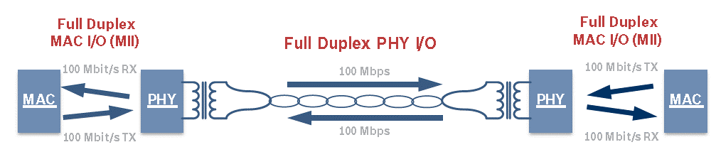
Full-duplex communication along with PAM3 signaling, while vital to the performance of Automotive Ethernet, add complexity in validating ECUs under real-world conditions. Most serial standards operate in a simplex mode with only one device communicating at a time, or there’s a separate link for the transmitter and receiver. With Automotive Ethernet, however, the Transmitter and Receiver device communicate simultaneously over the same link. (See Figure 2.)
As a result, the signals from the Transmitter and Receiver are overlaid on each other. Figure 3 shows an example of an Automotive Ethernet signal without the separation of the Transmitter and Receiver signals.
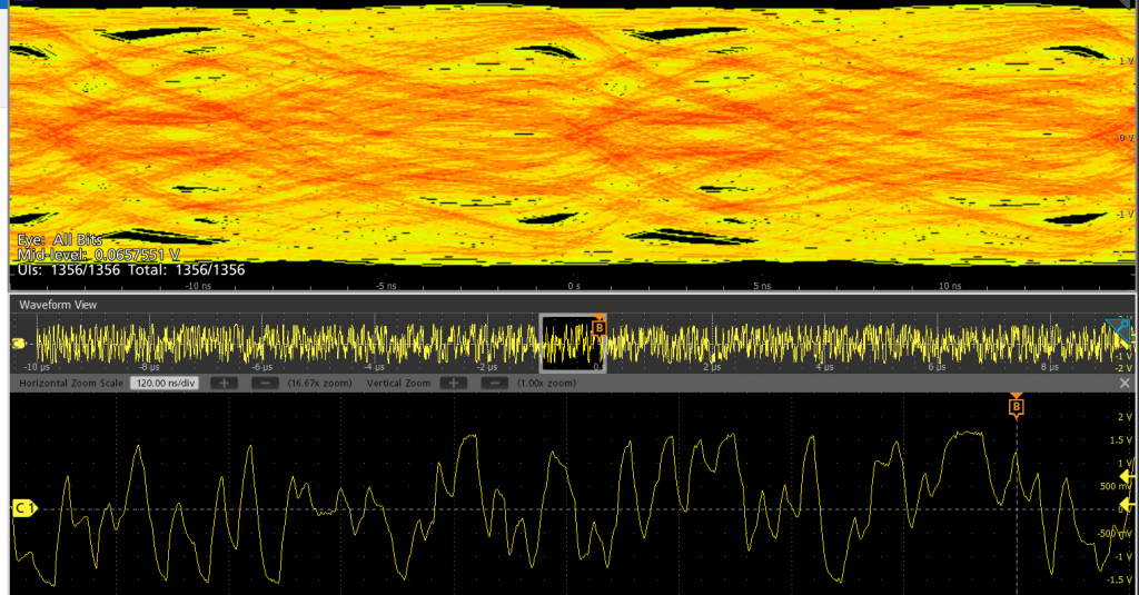
As this example demonstrates, in order to perform signal integrity analysis over a link, and protocol decode in system environment on an oscilloscope, automobile designers need to look at each link separately, which requires separating the signals before performing analysis.
Separating automotive ethernet full-duplex signals
Currently, there are two methods for separating Transmitter and Receiver signals. The first is the legacy method that requires cutting the Automotive Ethernet cable and inserting a directional coupler to separate and test the signals. This method has inherent shortcomings for accurate testing with minimal disruptions.
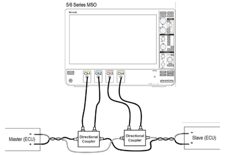
- The directional coupler approach requires cutting the Automotive Ethernet cable and inserting a directional coupler to separate the traffic. It is not easy to cut the cable at the system level, which makes this method less than ideal for most system level testing applications.
- While this approach does provide access to the Transmitter and Receiver signals, it introduces Insertion and return loss, which can make it difficult to determine if an error is a result of the system or the additional hardware.
- And, while it is possible to remove the effects of the directional coupler, de-embedding can amplify the noise in the system and impact measurement and characterization accuracy.
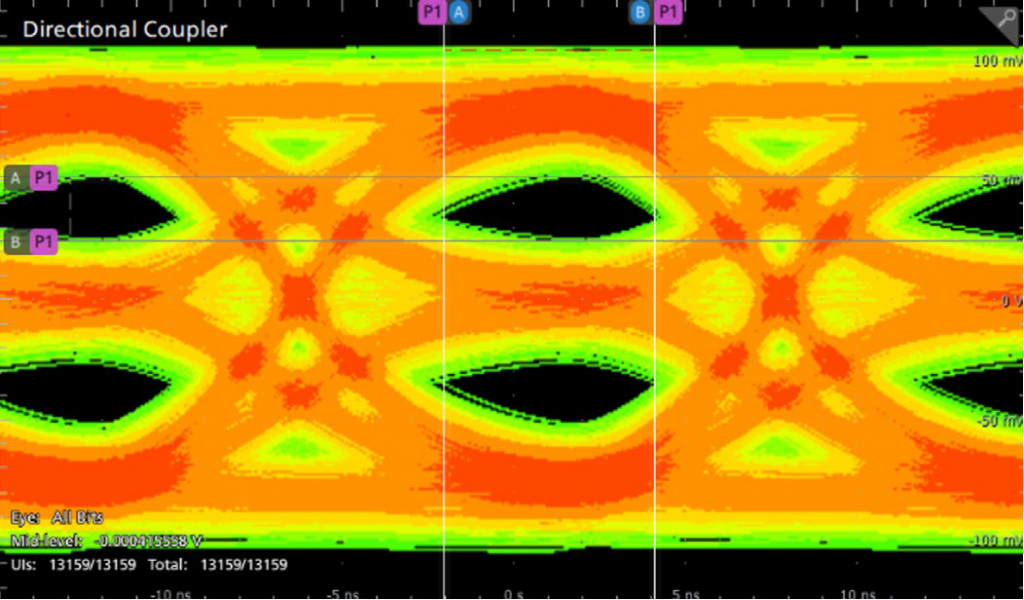
The eye diagram we obtained in Figure 5 illustrates the impact of insertion and return loss on Automotive Ethernet signals with a directional coupler installed. As is visible, the max amplitude is just 100 mVpp while actual Automotive Ethernet signal is 2Vpp, as the directional coupler and the insertion and return loss close the eye diagram.
Software based signal separation method
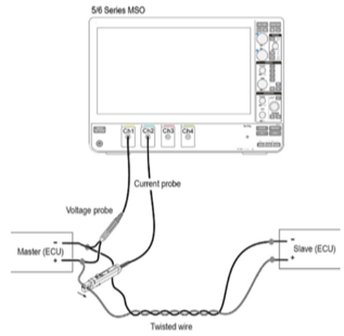
More recently, test manufacturers have introduced a new methodology that uses software and probes to non-intrusively separate the signals, allowing engineers to visualize the true signals with greater clarity. In contrast to the directional coupler which uses a hardware-based approach to separate the signals, the software approach separates the full-duplex signal by looking at voltage and current waveforms from both the Transmitter and Receiver test points and providing separated signals using software algorithms.
- Software-based solution eliminates cutting the Automotive Ethernet cable and displays Transmitter and Receiver signals without adding insertion and return loss. And there is no need to worry about de-embedding.
- Provides true signal to study signal integrity at system level
As shown in Figure 7, the software-based approach improves signal quality with “cleaner” eyes. This provides a much more accurate representation of Automotive Ethernet signals for signal quality measurements and improves the ability to identify potential performance issues in less time and with greater confidence.
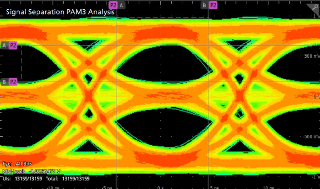
In comparison, the software-based method as illustrated here shows the true signal without disrupting the system. This solution is available for 100BASE-T1 as well as 1000BASE-T1 along with user defined Equalizers configuration.
This new Automotive Ethernet test methodology will allow engineers to characterize signals faster and more accurately without cutting cable or adding new hardware. This method overcomes many of the challenges associated with performing Automotive Ethernet signal integrity tests at the system level and opens up a wide range of new use cases that were previously very challenging or inaccessible.
System level protocol decode
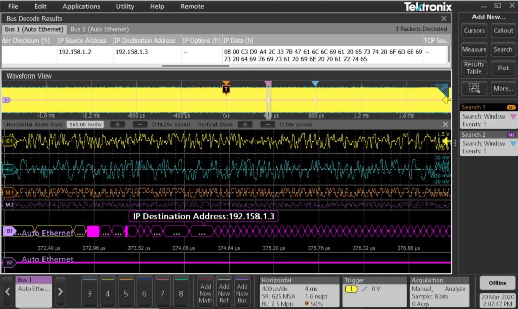
A software-based signal separation technique can be used for system-level Protocol debug as well. This method provides accurate Protocol decode without cutting the cable.
Summary: System level signal integrity test is very critical for High speed Network standards to meet reliability criteria. Software based signal separation technique allows user to uncover signal integrity issues before integrating the entire system. This helps designers to perform “What-if” analysis for Automotive Ethernet without impacting system performance.
Reference: Automotive Ethernet: See the True Signal https://www.tek.com/document/application-note/automotive-ethernet-see-true-signal
https://www.tek.com/automotive/automotive-ethernet

Darshan Mehta
Product Manager, Tektronix
He has specialization in the automotive sector, having over 19 years of experience in the test & measurement sector, essaying a multitude of roles in the automotive, mobile telecommunication, electronic & semiconductor industry. He has an insight into how modern test & measurement equipment can aid the engineers of today in creating the products of tomorrow.
Published in Telematics Wire