3D Model and BD Simulation of High Frequency Wireless Power Transmission by Resonant Inductive Coupling for Electric Vehicle Charging

Electric vehicles are spearheading the global transition of mobility towards sustainability. EV charging infrastructure is the most oversight space in the EV arena, on the other hand, Electricity is one of the least perfect things in the world until we cut the chords and end the age of tethering. Charging EVs without wires will be one excellent alternative for the EV charging and to accelerate the EV adoption around the world and further developing the technology that drives future generation transportation charging infrastructure and to make charging ecosystem easy, comfortable, safe and reliable to the users.
Charging of Electric Vehicles can be unwieldy when autonomous vehicles thrive in the market. The cords can get tangled, come under the vehicle or the parking spots can become limited by the range of wire. Wireless charging will be aesthetically pleasant, charging will be convenient and there will be no risk of electric shock to the user and can be automized. Finally, the future is wireless and the world is already moving towards a cord-free future.
For these challenging technologies like Wireless charging to succeed, we need an innovation-driven approach with strong technical solutions. A brief overview of the wireless charging technology 3D Model, Block Diagram and simulation is presented below;
3D Model of Static Charging of Electric Vehicles:

Wireless power transfer in electric vehicles may bring a profound change in the charging system. Plug-in Electric vehicles need cables & Plug charges but physical plug charges and Cables may become hassle and messy. With the system where we have to physically plug-in chargers, there are a number of occasions where the owners can often forget to charge the vehicles.
For stationary applications like charging of plug-in electric vehicles at home, Wireless transmission technology adds a convenient factor compared to actual plugging in. which means the vehicle will have a full charge every morning. By re-configuring, the transformer and altering the resonant frequency energy is transferred to the battery with lower energy losses.
Sufficient power for the battery can be transferred from the primary to the secondary circuit without significant energy losses. The electrical power is then transmitted to the battery which is electrically coupled to the secondary circuit through the air-core transformer.
Block Diagram of High-Frequency Resonant Inductive Coupling (HFRIC) Wireless Charging:
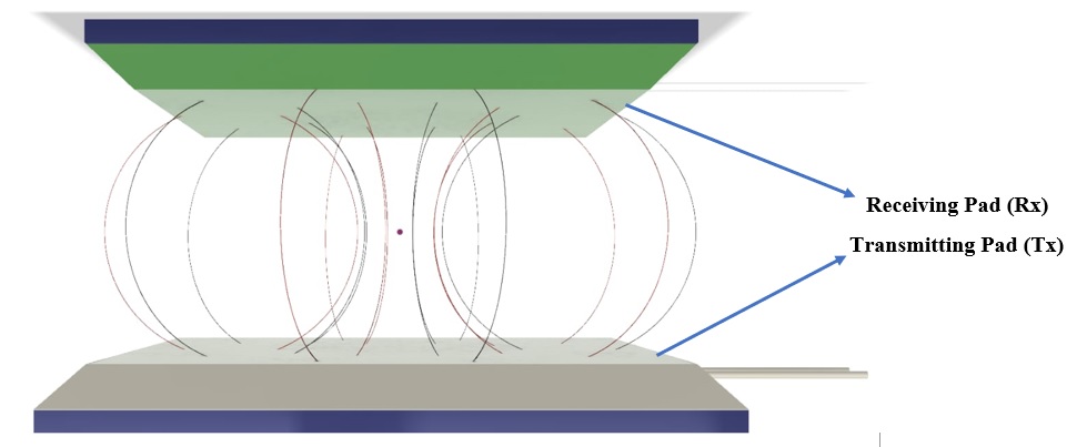
The Wireless Power Tx pad or The Transmitter pad contains a single loop of hallow copper tube which carries high-frequency alternating currents, in turn, producing high frequency alternating magnetic flux around it, the range of flux depends upon the resonant frequency. Along with the single loop of hollow copper tube, there will be supporting power electronic components which are responsible for producing high frequency signals, AC/DC conversion, power conditioning, DC/HFAC conversion (Square Wave), Impedance compensation or resonance tuning.
The Wireless Power Transmission system consists of a power source which is a high-speed switching circuit for generating high frequency signals, primary impedance compensating network and primary magnetically coupled coil; all these components put together to form transmitter circuit.
The Wireless Power Rx pad or The Receiving pad contains a single loop of hallow copper tube which receives high-frequency alternating flux from the transmitter coil, in turn, producing an EMF in the secondary circuit. The receiver circuit comprises of secondary magnetically coupled coil, a secondary impedance compensating network, a high frequent rectifier, a voltage regulator.
There are many power electronic components which recondition the power received from the receiving coil. The high-speed switching circuit is one of the main blocks, a high-frequency resonant inverter that comprises of power MOSFETs and gate trigger circuits. A power MOSFET is a Metal Oxide Semiconductor Field Effect Transistor (MOSFET) designed to handle significant power levels and can operate at high frequencies in the range of hundreds of kilohertz. With the advancement in the field of power electronics a new power MOSFET (SiC MOSFET) that can operate at frequencies up to Mega Hertz which is used for high-frequency switching applications.
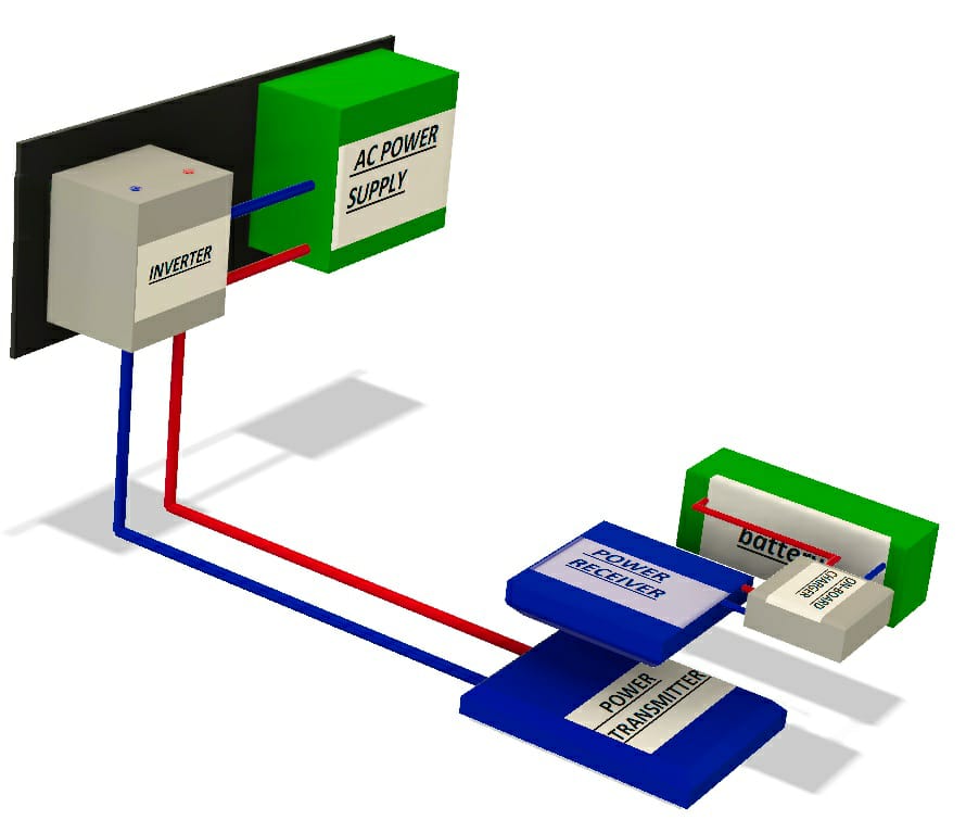
The major blocks of HFRIC Wireless Charging system are the power inverter and the resonant magnetic coils which are responsible for efficient and reliable power transmission. When the receiver pad comes in the vicinity of the transmitter the power transmission happens at resonance. The receiver which is retrofitted below the EV picks up the transmitted power, the received power is then used to charge the battery in the electric vehicle.
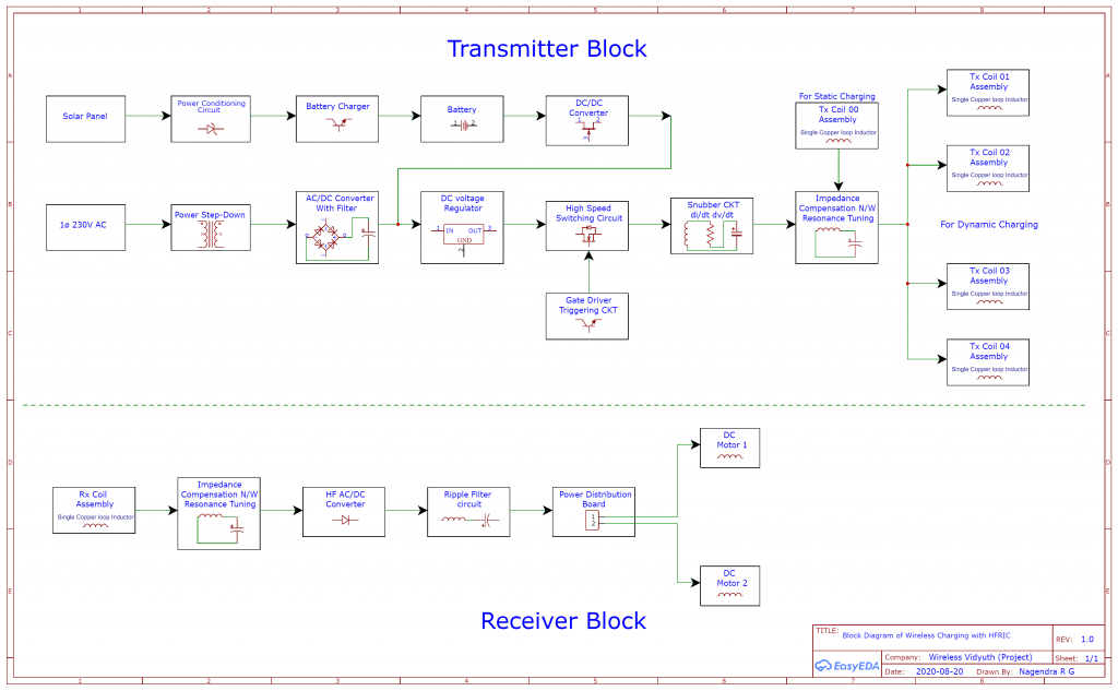
A detailed block diagram with discrete transmitter and receiver blocks
The Wireless Power Transmission system consists of a power source which is a high-speed switching circuit for generating high frequency signals, primary impedance compensating network and primary magnetically coupled coil; all these components put together to form transmitter circuit. And receiver circuit comprises of secondary magnetically coupled coil, a secondary impedance compensating network, a high frequent rectifier, a voltage regulator and a DC load. The highspeed switching circuit is a high frequency resonant inverter that comprises of power MOSFETs and gate triggering circuits.
The impedance matching network has a significant role in Wireless Power Transmission system. The impedance matching network reduces the VA (volt-ampere) rating of the power source by minimizing the reactance of input impedance and increase the power transmission efficiency by utilizing the magnetic field resonance. The time varying magnetic field is generated from the primary coil and is transmitted to the secondary coil. A high frequency rectifier is used to convert high frequency AC power into a DC power.
The Transmitter block contains series of circuit topologies, Tx00 block indicates the transmitter coil for static charging and Tx01 to Tx04 is for dynamic charging. In the Receiver block, everything will be mounted on a small car powered by 2 motors no battery is kept for the clear demonstration of wireless charging. The demo car may be controlled by a relay mechanism or a wireless control system. The main intention is to demonstrate both static and dynamic charging concepts with the same circuit elements.
A coil of High Q-Factor copper tubes or copper wires can be used, but with the high-frequency circuits only hallow copper tubes are recommended to avoid skin effect. A special type of MOSFET called SiC MOSFET will be used to reduce switching & heat losses.
There are two losses associated with the diodes in a high frequency rectifier; losses due to the forward conduction of the diodes and the high frequency loss according to the switching time of the diodes. These losses act as the reverse recovery time for the diodes. To eliminate these losses, Schottky diodes or ultrafast diodes are used in the rectifier circuit instead of normal 1N4007 diodes. The voltage regulator is used to stabilize and control the DC voltage level according to the required load voltage.
Simulation of Schematic Diagram of a Wireless Power System:
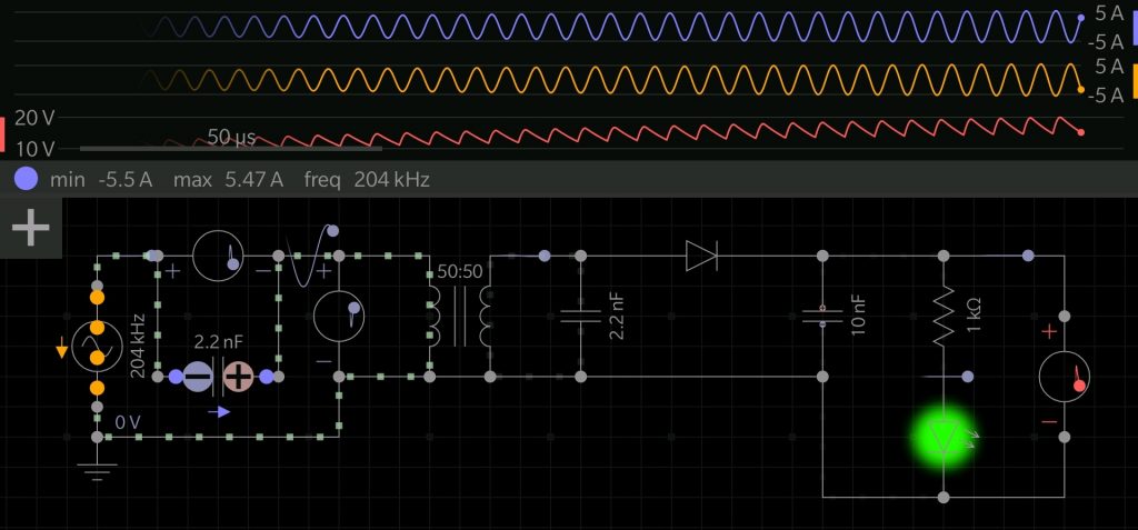
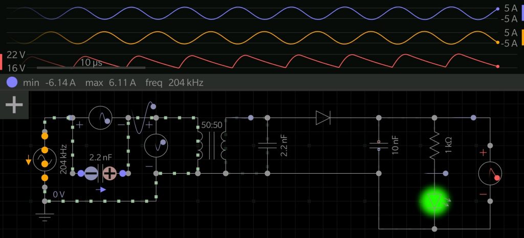
The above Schematics shows the hardware model and simulation results of Inductive coupling. In this project, Wireless Power Transmission for EV charging is done by using inductive coupling technique.
In this, we have converted AC voltage at the input to DC voltage using a rectifier. The power is transmitted from the transmitter to a receiver as DC voltage due to mutual induction principle. The simple working prototype of a wireless power transmission system require some copper wires for making primary and secondary coils which may be of same turns, a transistor which acts as a static switch and a capacitor is connected at the receiving coil. The basic theory behind this includes the inductive energy that is transmitted from a transmitter coil to the receiver coil through a magnetic field. The transmitter coil is connected to a power source through a high-speed switching circuit. The magnetic field links with the secondary coil and induces an EMF on the principle of Faraday’s laws of Electro-Magnetic induction. In the receiving coil, a capacitor may be connected for maintaining the output constant.
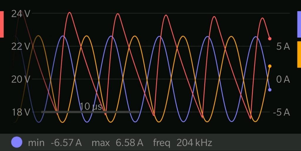
The circuit works at a resonant frequency of 204KHz and the value of current is varying according to the load in the secondary. In the first image, Imax is 5.47A at 20V viewing at 50 micro-seconds. In second image Imax is 6.11A at 22V viewing at 10 micro-seconds. With 22 nano-farad on both the ends creating a resonant frequency of 204KHz. No static switch is used as a function generator is used for the demonstration purpose.
Future Scope: Dynamic Charging using High-Frequency Resonant Inductive Coupling
Dynamic charging in simple words means charging of the electrical vehicles even under the movement in electrically equipped roads. In larger cities, dynamic charging offers an even greater impact utilizing existing infrastructures as vehicles travel along the busy freeways wireless charging can also occur while the vehicle is in motion. The transmitting plate kept under the road will be ON only when the vehicle passes over the plate (the vehicles having to receive plate comes into the area of transmitting plate it turns on) this is known as a segment control technology. The power lines are managed by Segment Control Technology, which supplies power to the vehicle only when it is passing over the power line. This technology prevents a magnetic field from being generated while pedestrians walk or other vehicles run on the road as well as wasting energy.
Dynamic charging allows electricity to supply a very large fraction of the energy for the transportation sector and reduce considerable petroleum consumption. Previously traffic delays now provide of charge while passing over in motion charges.
Norway’s appetite for electric cars is booming, and its capital of Oslo will be the first to install wireless charging infrastructure for the city’s electric taxis. Oslo, Norway has recently become the world’s first city to start setting up city-wide wireless charging infrastructure for EVs. While waiting for customers at the stands, the taxis will charge via induction. Its wireless charging infrastructure is built to solve the issue of taxi drivers searching around for chargers and waiting to charge. U.S Department of Energy in collaboration with Oak Ridge National Laboratory is developing Wireless chargers for Evs. Also, BMW is building its own wireless charging system for its EVs.
Conclusion:
The transmission of power without wires is not just a theory, it is now a reality and in future, it should be made available for a large number of EV charging. EV Charging infrastructure can be seen more in urban and dense urban areas but if there are more charging stations spread all along the cities and high ways, makes range anxiety fade with the users and with assured charge points. The 3D model and the Simulation results give a brief overview of modelling a sample High-Frequency Resonant Inductive Coupling wireless power schematic for charging EVs and opens-up a new dimension for future research and dev elopement of the technology with adroit innovative solutions for an unwired future.
Author:
Nagendra Gouthamas
Nagendra is a passionate electrical engineer, inspired by a great scientist Nikola Tesla. He is Co-Founder of an early-stage Global Project called Wireless Vidyuth at Bengaluru, aspiring to become a full-fledged Clean-Tech Startup. Nagendra is a certified IoT designer from Stanford University and University of Helsinki and he has been involved in European Graphene-Battery flagship program. He is extremely zealous in building a viable, efficient and cost-effective wireless charging solution for charging EVs.
Published in Telematics Wire


Very good Presentation With Autentication Information.Young Scientist in the Field of Energy is a Bright Future!All the Best Nagendra!