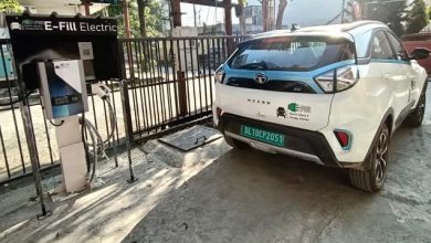
Battery Driven Vehicle is not a very new concept. The traces of EV technology can be found even in the initial years of automotive development. But modern-day automobiles are much more capable in terms of Power, Range, Comfort and Advance features like ADAS and connectivity. Also, the high voltage battery of modern EVs perform very complex tasks ranging from electrical monitoring and control to data analysis and predictive maintenance activities.
All of this is mostly being done by increasing use of electrical and/or electronic (E/E) systems and software.
How much complex is it actually?
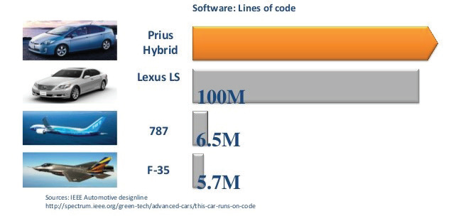
During IEEE Spectrum, according to professor Manfred Broy, a modern luxury vehicle “probably contains close to 100 million lines of software code” and these software are processed by up to 100 microprocessors networked throughout the car.
Just to put the modern automobile E/E complexity into some perspective, the Ford GT car has approx.10 million lines of code, which is about eight million more than what Lockheed used in the F-22 Raptor fighter jet, and at least three million more than Boeing puts in its 787 Dreamliner.
Because the features provided by these E/E systems are must to have for modern automotive buyer, the vehicle manufacturers are trying hard to bring the latest innovations through their products before their competitors.
This increasing complexity, shorter time to market and lack of experience of these technologies is leading to the increasing number of unknowns in the automobiles. The complex multilayer supply chain in automotive industry increases this challenge further. Because the final vehicle manufacturer may not design and develop all the subsystem and child components. The proprietary technologies of component supplier and their supplier, when integrated in a vehicle manufacturer specific architecture and then the vehicle is run in numerous environments and driving conditions, may or may not behave as expected by the tier 2 or tier 3 supplier.
Possible Impacts:
Some fire incidents in the EVs and accidents due to the autopilot (ADAS) systems are the evidence of this fact. Recently one of the world’s biggest EV manufacturer recalled around 159,000 luxury EVs due to Worn Out Memory Chips resulting in Infotainment System and ADAS Cameras malfunctioning. There are many incidents of such types at different scales with different vehicle manufacturers.
The stakes are high. Because, unlike the failure of a cell phone application or a website or many other products, a vehicle system failure may lead to fatal incidents and the possible impact is huge. From human life/health to hefty sum of money, and from the brand value of the company to the trust of customers on the underlying technology, all may get a hit.
ISO 26262 at rescue:
To overcome these challenges and mitigate the failure of E/E systems that are installed in cars with a maximum gross vehicle mass up to 3500 kg, ISO 26262 standard is designed. ISO 26262 addresses the whole product development cycle and can be easily mapped to the ‘V-Model’ of product development. The following diagram shows the 10 chapters of ISO 26262 mapped to the V-Model. It can be noticed that apart from core development processes, management and supporting processes are also covered in this standard, which makes it comprehensive and single point reference for functional safety analysis of E/E systems.
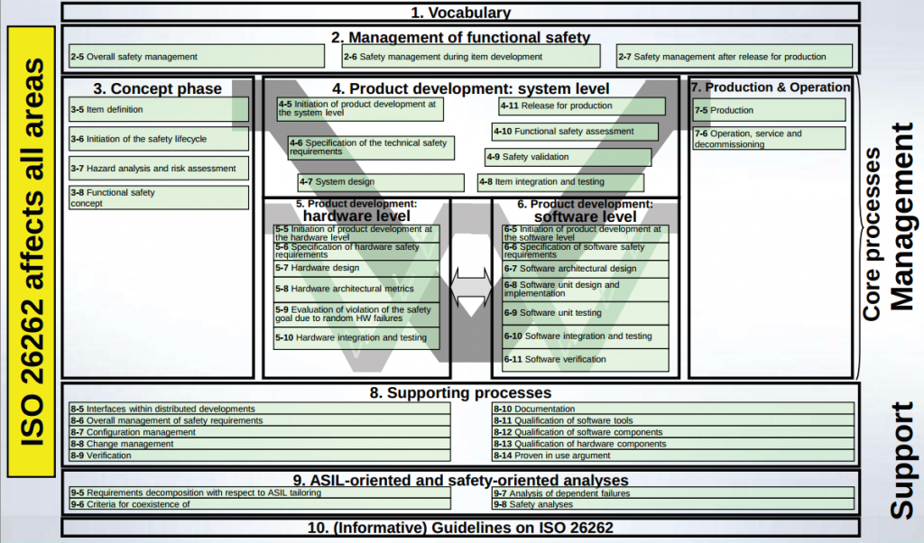
Another noticeable fact is that, while the traditional V-Model focuses on the concurrent Development-Test activities, the ISO 26262 adds the functional safety as third concurrent dimension in each step of V-Model.
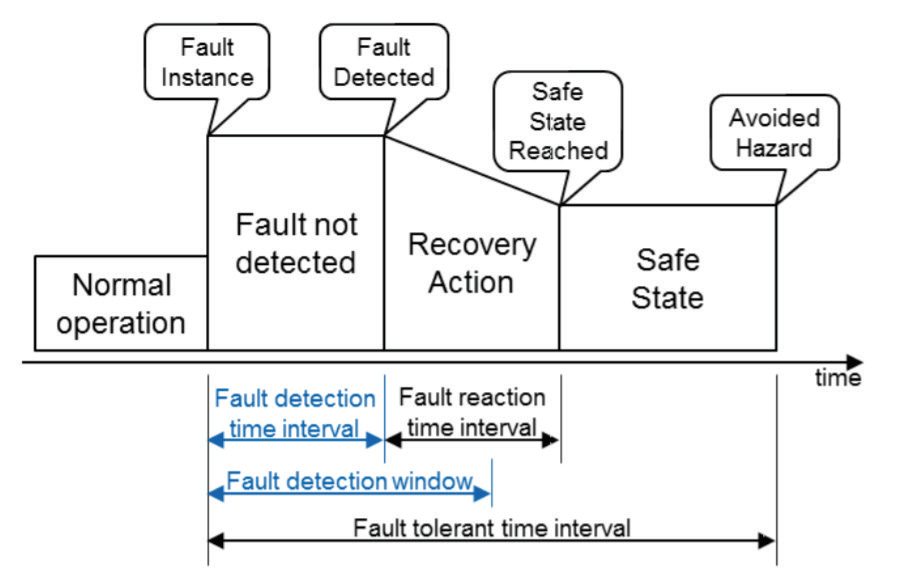
ISO 26262 helps in identifying quantitative and measurable parameters in each of the process steps so that the stakeholders can make decision easily. For example, in first chapter of ISO 26262, the classification of various fault-time related parameters is done as following figure:
Second chapter mentions about the requirements for the organisations that are responsible for the safety lifecycle. The safety management is required during product development and even after the product release as well.
The third chapter is the start of core development phase and related functional safety activities.
It starts with a crucial steps of Item definition. Item definition defines the interfaces, functionality, environment conditions, known hazards and legal requirements etc.
HARA and ASIL:
After item definition, the new development and the modification in existing system are identified. Next step is to do the HARA (hazard analysis and risk assessment). This activity aims to categorise the hazards that can be resulted from the malfunctions in the system. The hazards are categorised on the basics of Severity of damage caused by the hazard (S0 to S3; S0 being least severe and S3 the most), Controllability of the event by user (C0 to C3; C0 being most easily controllable) and probability of exposure of the hazardous event while product is in use (E0 to E4; E0 being least probable).
This is done according to the different possible use case scenarios of the vehicle in different environmental conditions. An ASIL (Automotive Safety Integrity Level) is assigned to each hazardous event. Four ASILs are defined ASIL A, B, C and D, where ASIL A is the lowest safety integrity level and ASIL D is the highest one. An additional class QM (Quality Management) denoted no requirement to comply with ISO 26262.
Safety goals are determined for each hazardous event with ASIL evaluated. Safety goals are functional objectives. These are top level safety requirements for the items and lead to functional safety requirements.
Now the functional safety requirements are derived from the safety goals and allocated to preliminary architectural elements of the item or to external measures.
Note: Detailed examples of Severity, Controllability and Exposure classes are provided in ISO 26262 chapter 3, which can be used and edited according to the specific applicability of target product. Also, the chart for ASIL level determination from the combination of Severity, Controllability and Exposure classes is mentioned.
System Design
The fourth chapter (Part 4) carries forward these safety goals allocated to preliminary architectural elements and takes care of this during the system design.
To design a system which complies with the technical safety requirements at their respective ASILs is a major activity of this phase.
To avoid systematic failures, both deductive analysis methods such as FTA and Ishikawa diagrams, and inductive analysis methods such as FMEA, ETA and Markov modelling etc. are used mostly with qualitative analysis. For lower ASIL items, Inductive analysis only is required. For higher ASILs, both methods are to be applied.
ISO 26262 Part 5 and beyond:
The later phases of ISO 26262 are about these requirements and analysis results are implemented well, keeping all the hardware-software and interface development processes, tools, testing, verification and validation in mind. Also, the audit and traceability guidelines are mentioned.
List of interfaces such as Memory types, converters, communication buses, timers, electrical I/O and multiplexers etc. is mentioned along with the characteristics such as interrupts, timings, network modes and initialization etc.
Production and operation guidelines (Chapter 7) and other supporting guidelines (Chapter 8, 9 and 10) are also very useful in ensuring overall safety of the EE system.
New horizons:
New special purpose functional safety standards are also evolving in parallel to ISO 26262. e.g. SOTIF (Safety Of The Intended Functionality) ISO/PAS 21448:2019 for the systems involving AI-ML and Neural Networks, and TARA (Threat Analysis and Risk Assessment) for cyber security for connected vehicles.
Conclusion:
We can see that by adopting ISO 26262 guidelines, the complex E/E system can be analysed in a simplified and systematic way to ensure a certain level of confidence in terms of reliability of these systems. Organisations of today need to pay proper attention to product safety and security in order to avoid the perils of mishap due to E/E system malfunctions.
References:
- Google image
- ISO 26262 Part 1, First Edition, “Figure 1 – Overview of ISO 26262”
- ISO 26262 Part 1, First Edition, “Figure 4 – Fault reaction time and fault tolerant time interval”
- NHTSA Tech Note: TN-13-44-003, June 26, 2013
Author:
Vijay Pratap Singh is an automotive system engineer with 7+ years of experience in product engineering. His major work areas include system engineering, functional safety analysis, software development, IVN management, diagnostics and vehicle integration. He is new technologies enthusiast and like to read about economy and psychology apart from technology.
Published in Telematics Wire