
Active safety systems are becoming standard equipment in more and more vehicles. These systems rely on accurate information about the environment around the vehicle. This information is acquired using a whole suite of sensors. For Autonomous Vehicle’s (AVs), Radar is a prevalent sensor to perceive the vulnerable road users/objects and can be easily integrated to estimate range, velocity, angle, and some cases elevation height of the target objects with respect to ego vehicle. Automotive Radar is the key sensor to evaluate relative velocity of the intended target.
Front cameras (SMPC or MPC) mounted high up behind the vehicle windshield dominate currently in ADAS applications like the lane/object detection and its related areas. However, the performance of the camera degrades when it encounters extreme lighting conditions. This degradation may not only be caused by adverse weather conditions like heavy fog, haze, rain, snow, etc., but can also arise out of challenging lighting conditions like the strong head- or taillight from other vehicles, the glaring sunlight from the sun. In some critical scenarios may be problematic for camera alone to detect, like the sudden change of the lighting when a vehicle drives into or out from a tunnel on a bright day, etc.
Historically Radar is associated with World War 2 technology. With advancements in Semiconductor technology and miniaturization, it got integrated into vehicles as a warning-based system. This was good enough for a highway scenario in certain geographies. Today, the world is transitioning from L1 to L2/L3 and even higher degrees of autonomy. With various mishaps in which AVs were entangled in their recent rollout phase from different OEMs, the need for Imaging Radars got emphasized.
Being a reliable, all-weather sensor, the world is expecting Imaging Radars to deliver on counts of High resolution and a sensor which can be used in conjunction with Camera to produce a real-time reconstruction of the surroundings. In Essence, replacing human eyes on the road. Such a technology would also find use in many other applications. The key technical challenge of the automotive radar system is resolution, and classification in dense environments in all dimensions of space and time
Since the advent of the Adaptive Cruise Control (ACC) application as part of Advanced Driver Assistance System (ADAS) at the end of the last century, radar sensors became more and more essential in the ADAS automotive area. The advantages of radar sensors (insensitive against dust, fog and darkness as well as instantaneous speed measurement) were quickly recognized and used in many ADAS, like Lane Change Assist (LCA), Rear Cross Traffic Alert (RCTA), Blind Spot Detection (BSD) or Automatic Emergency Braking (AEB). With the increasing level of applications complexity in ADAS, the demand on the imaging radar increases too. With these advanced imaging radar, the recognition of relatively small objects like pedestrians, cyclists, and stationary objects in a dense urban environment would be possible in more efficient manner than the conventional radars as shown in the below Figure 1.
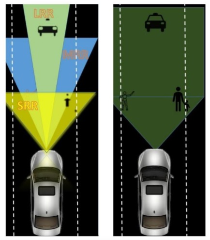
Fig.1
Steradian Semiconductor Imaging Radar
Steradian Semiconductor has a proven track record of building Ultra-High-Resolution Imaging Radar solutions, with the current generation on the market offering 256 Multiple Input and Multiple Output (MIMO) channels. In addition, the developed module has capability to accomplish superior resolution (3cm range resolution and 1-degree angle resolution) at 15fps (Frames per second) (online) and 20fps (offline) for 50-meter distances. The module is a generation ahead of the present market solutions positioned at 10cm range resolution with range of only 20 meters. The module is able to manage massive data efficiently while enabling a real-time ultra-high resolution. In addition, with simply changing the software, the same platform can be used for LRR application offering tracking of objects till 300-meters distance. The simple block diagram of the steradian developed imaging radar SW stack is given below Figure 2. This high-resolution radar can be used for multiple fields, and not only ADAS, like traffic monitoring, human motion detection, security application without compromising on the privacy. IRU256V1 uses Frequency Modulated Continuous Wave (FMCW) modulation for its operation while extracting range, velocity, and position of the target to a very high degree of accuracy. A typical FMCW chirp configuration can be seen in the below Figure 2(b). The maximum frequency change in the echo signal with respect the transmitted signal provides velocity and range information, thereby placing the target in a relative sense to the ego vehicle.


Fig. 2 (a)Simple block diagram of Imaging radar IRU256V1 and (b) typical FMCW chirp and target echoes
IRU256V1 has self-test routines for customer debug and easily configured for different applications and platforms as it is designed for more generic software and hardware combination for range of possible applications. The RF front end of the radar unit is critical in deciding the radar overall performance. In front end, CMOS Radar IC is key module where all transceivers, registers, memory, and other routines for output data are implemented. Salient features of the IRU 256V1 sensor are summarized below:
- Single Radar unit for LRR and SRR at 76-81 GHz.
- Multi-Mode characteristics with ease of configurations.
- Real time Point-Cloud or tracked objects as the output.
- Based on SVR4410 High Performance CMOS Radar IC.
- Mapping of both stationary and moving targets.
- 256 Aggregate MIMO channels (16 Transmit and 16 Receive channels.)
- Azimuth and Elevation Scanning.
- Compact Size of 16.8cm × 11.4cm × 3.48cm
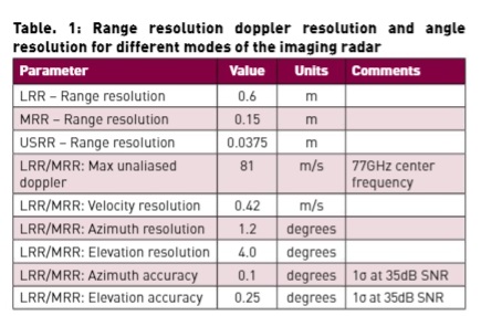
- Resolution details for different modes of the radar are tabulated in below Table 1
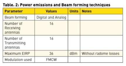
- Power emissions for different modes are as per the standards and given in below Table 2
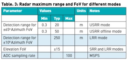
- Maximum range for different modes and their Field of view (FoV) in both azimuth and elevation are given in Table 3
Steradian Semiconductor is developing radar systems based on Hybrid Beam Forming (HBF) technology to integrate features like multi-mode configurations and application flexibility. As the operating frequency is 76 GHz and above, to avoid any losses associated on the packaging layout, PCB dielectric and conductors need to be carefully designed. From feedline to the antenna losses are minimized by avoiding sudden changes in the signal transmission paths (bends) and impedance matching techniques. Below Figure 3 shows the feedline line characterization by varying the width and length of the feed line to estimate characteristic impedance and guided wavelength at 79 GHz. The antennas are designed based on low loss substrate with dielectric constant 3.3 and loss tangent of 0.001. In the process, once the feed lines are characterized for desired impedance, antenna is fed through the feed line with minimal insertion loss and minimal impact on the radiation pattern.

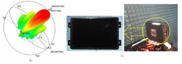
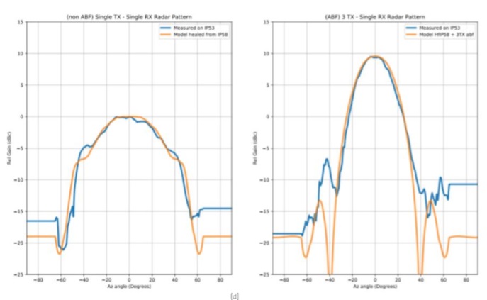
As shown in below Figure 4 (a), (b), antenna exhibits wide azimuth and narrow elevation radiation pattern with high gain and low side lobes to cater the ADAS functional requirements. The antennas are designed based on series fed linear array with end feed technique. As mentioned, IRU256V1 has different modes of operation with different field pattern and intensities are facilitated through exciting multiple antennas simultaneously. Figure 4(c) shows the measured two-way magnitude pattern of the module with single transmitter- single receiver antenna channel and three transmitter-single receiver antenna channels. Modeled pattern and measured pattern are correlated with each other.

Radar IC is key component in the imaging radar, as it has transceiver modules for the respective MIMO channels. IRU256V1 uses fully integrated 16 channel E-band MIMO radar transceiver. Figure 5 shows the image of the Radar IC. This module has 19 dBm transmitting power and capable of high precision beam steering. The noise figure of the receiver channel chain is 8dB and can support the 100 MSPS ADC.

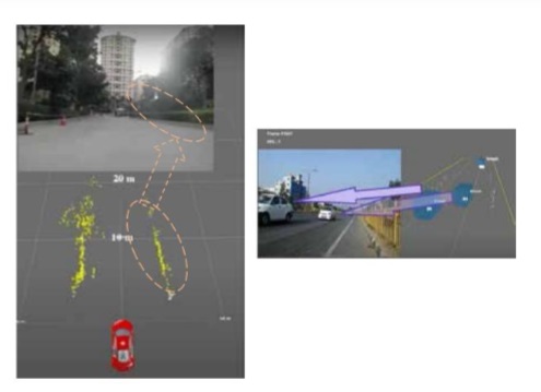
IRU256V1 device firmware runs from another host controller, enabling all the functions of the RF front end module or RFIC communication with Analog to digital converter (ADC) and GPU based processor. The firmware package that provides continuous monitor, control, and configuration for chirp Band Width (BW) and frequency as well as transmitter sequencing synchronization with the external world has been controlled in real-time. The processed point cloud for the scene in the image is depicted in below Figure 6.
Conclusion
With higher resolution and superior object detection, classification, and tracking in all environmental conditions makes the IRU256V1 a promising candidate for automotive AV/ADAS and other industrial applications. Tracking algorithm tracks all the objects physically small in size such as pedestrians, bicycles, scooters, in the vicinity of stationary objects like a parked vehicle and even traffic cones. The Imaging Radar is reliable to integrate ADAS and AV systems for perception of the environment as it can minimize false alarms, which are prevalent and undesirable with radars. An important design aspect of the imaging radar is to detect of the vulnerable road users thereby bringing safety at the core of the solution. The formfactor of the module is low to integrate in the AVs. An imaging radar with 256 channels is state-of-the-art and competent for the market. Summary of the IRU256V1 imaging radar specifications are given in below table.
| S. No | Features | Description |
| 1 | 4D Imaging | Antenna 6.5° elevation beam width |
| 2 | Multimode support | Wide field of view of 120° in azimuth and 30° in elevation |
| 3 | Quick evaluation | GUI for data collection and FoM testing. |
| 4 | Realtime application | 15 fps refresh rate through standard ethernet interface |
Authors:
Dr. Anil Kamma holds M.Tech and Ph.D. in the field of RF and Microwave Engineering from Indian Institute of Technology Bombay (IIT Bombay), Mumbai. He joined Mercedes Benz Research and Development Pvt. Ltd (MBRDI), Bangalore in 2017 as a Senior Technical Lead and was instrumental in developing Radar Integration and EM simulations process. He is an author and co-author for 8 Journals,15 conferences and a patent. He is an Eiffel Excellence Scholar by the French Ministry for Europe and Foreign Affairs and CST university publication award winner.
Ashish Lachhwani is a 2004 Institute Silver Medalist from IIT, Madras. He joined Texas Instruments (TI), Wireless Group in 2004 and was instrumental in developing 2 generations of TI low power Bluetooth Radio solutions called SimpleLink. He is a co-author for the book on Ultra-Low-Power Radios published by Springer. Ashish was the Frequency Synthesizer architect of Qualcomm Snapdragon 65x RFIC. He holds 8 issued patents.
Rakesh Kumar is an alumnus of Delhi College of Engineering and has a proven track record of building lowest area RFIC. Rakesh led the WLAN RF for 2 generations in Texas Instruments. He was the Receiver lead for Snapdragon 65x RFIC of Qualcomm. He has wide experience in developing complete solution including Firmware & Systems. He has co-authored 2 IEEE papers and holds 8 issued US patents.
Published in Telematics Wire