- Overview
As our everyday gadgets become ‘smart’ the need of ‘communicating’ with them multiplies. LCD (Liquid Crystal Display) greatly helps this communication by ‘telling’ the gadget’s story. A touch panel further enhances these conversations!
While LCD displays enable effortless communication for the end users, designing LCD displays in the gadgets is by no means an easy feat! As more and more gadgets need a LCDs built in, system architects, designers and engineers are tasked with the selecting and designing the appropriate LCD for their application. This task could be daunting given the wide array of LCD features available and the several system constraints to consider.
This article aims to assist system architects, designers, and engineers to decipher LCD vocabulary and choose the right display for their application.
- LCD Module Structure
From mechanical point of view, LCD module (LCM) can be understood as the stack-up of LCD panel and Backlight unit.
2.1 LCD panel
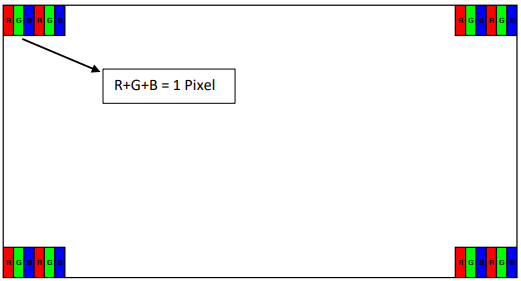
Overall, LCD panel could be simply understood as a matrix of windows, and each window consists of 3 small windows with Red, Green and Blue color.
In this case, each window is called as a Pixel, and each small window is called as a Sub-Pixel.
The array of pixels, such as 1366x 768, is called Resolution.
Mechanically, LCD panel consists 2 layers of glasses, TFT (Thin Film Transistor) glass and Color Filter glass. And Liquid crystal (LC) is sandwiched in between by 2 glasses. Polarizers are laminated on top and bottom of the LCD glass.
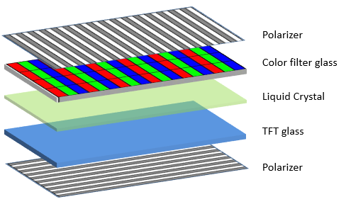
- TFT glass is coated with matrix of transistors as the control to each sub-pixel. That is where the name of TFT LCD comes from. On this point, TFT LCD is considered as active control, while monochrome LCD is passive control.
- Color filter glass is coated with matrix of phosphor with R, G and B color for each sub-pixel. R, G and B color will be generated when backlight passes through each sub-pixel, and various colors could be displayed with combination of different R, G and B levels.
- Physically, Liquid Crystal (LC) is a mixture of crystal molecules and chemical liquid, and distributed uniformly in the cell of each sub-pixel. The molecules in each sub-pixel will turn to certain angle according to the different voltage provided by TFT
- TFT glass and color filter glass are bonded together as LCD glass. Polarizers are laminated on top and bottom of LCD glass with perpendicular polarity.
Looking at the LCD glass as matrix of windows again and polarizers as shutters, theoretically, without liquid crystal, there will be no light passing through from back to front side as two shutters are installed with perpendicular angles. Here comes the characteristic and functionality of liquid crystal.

Above is the simple model of TN (Twisted Nematic) type of LCD in free running mode.
Backlight is polarized by bottom polarizer with 0° polarity. When it passes through the liquid crystal, the polarity is changed by the molecules little by little and finally becomes 90°. As a result, the light will be allowed to pass through top polarizer with 90° polarity.
- Backlight
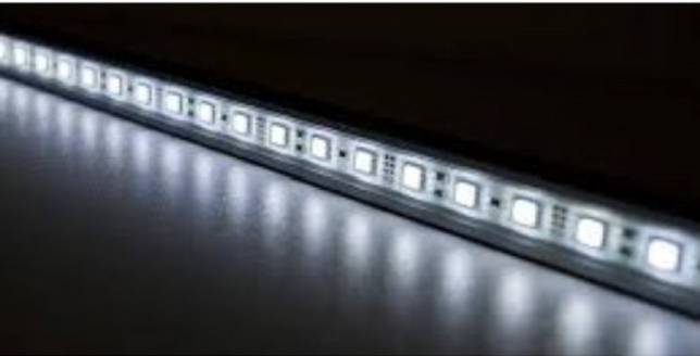
LED started to replace CCFL (Cold Cathode Fluorescent Lamp) some years back as the backlight source for LCD. And thanks to the optics technology improvement on light guide and optical films, LED bar could be placed on side of backlight unit to achieve good uniformity. As a result, the thickness of backlight thickness has been reduced to achieve slimmer design.
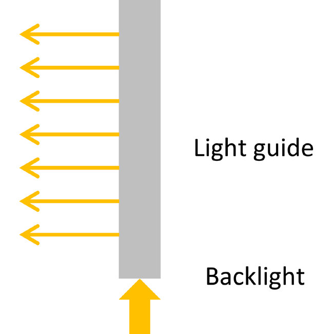
In the illustration above, Light guide will help distribute the light uniformly to the whole display area. Above it, Prism film will help improve the light transmission efficiency, and Diffuser films will help improve the uniformity and viewing angle. Furthermore, Reflection film will be used for light recycle and DBEF (Double Brightness Enhancement Film) could be used to enhance the brightness to improve the efficiency and finally achieve power saving.
In most of the application, backlight dimming will be applied for power saving purpose. For TV developers, backlight dimming could help to improve the dynamic contrast ratio as well.
- LCD specification
In this chapter, pertaining on the general LCD specification, we will try to list down most of the items for LCD requirements and sourcing.
- Screen size
Screen size is measured in diagonal on Active Area of LCD. The unit is normally in inch.
- LCD type and Display Mode
According to different LC arrangement, there are mainly 3 types of LCD, namely TN (Twisted Nematic), VA (Vertical Alignment) and IPS (In-Plane Switching).
In free running mode (with power supply but no video signal input to LCD), TN type of LCD will display full white, while VA and IPS type will display full black. So in LCD spec, you can see in normally white or normally black on the summary page.
- Resolution, Aspect Ratio and Orientation
Resolution refers to the number of pixels of LCD, normally described in matrix format, such as 640×480 (VGA), 1024×768 (XGA), 1366×768 (WXGA), 1280×720 (HD) and 1920×1080 (FHD).
The column of the matrix is called Source, to input the video signal for each sub-pixel. And the row of the matrix is called Gate, to control On/Off of each pixel line. ICs to control the columns are called Source Driver IC and ICs to control the rows are called Gate IC. Of course one single IC might be able to control both source and gate in some designs, such as the ones with lower resolution.
In most of LCD design, RGB sub-pixels are aligned in vertical stripes. So the number of source channels will be 3 times of pixel numbers in vertical. Taking 1920×1080 (FHD) as example and assuming each source driver IC can support 960 source channels, totally 6pcs of source driver ICs will be required in the panel.
Normally each pixel will be designed as square shape in TFT LCD (some monochrome LCD might be the exceptions). So we can easily understand the Aspect Ratio based on resolution. For example, the aspect ratio of VGA panel is 4:3 and FHD panel will be 16:9.
By default, if we talk about resolution such as 640×480, the Orientation of the LCD is landscape. Some vendors may indicate 640(RGB)x480 in spec for clear information. In this case, if we talk about the resolution of 480×640, it means the LCD is designed with Portrait orientation. In this case, the aspect ratio of this LCD is 3:4.
- Brightness
Brightness refers to the luminance when LCD displays full white. For reference, the LCD for normal Notebook is around 250nits, and TV panels are around 500nits.
The products used outdoors may require LCD brightness to be over 1000nits.
- Color
Color is a key and interesting factor on LCD.
Color depth refers to the bits of color, but does NOT indicate the color saturation directly. It could be understood as ‘resolution’ of color. For example on 24-bits color depth (8bits for each color), each sub-pixel can display 256 levels of single color. So the total number of colors that the LCD can display is 16.7M.
Color gamut is to define the color range that LCD can produce. Below figure shows the color gamut of NTSC, sRGB, Adobe RGB and DCI-P3 in CIE 1931 color chromaticity. Referring to the triangle area enclosed by each RGB, we can know the percentage it covers compared with the whole color chromaticity. One or two of the color spaces may be chosen to define the color gamut of each LCD design.
For reference, the color gamut for normal notebook panel is 45% of NTSC, and it is around 72% of NTSC for TV panels.

Color temperature (T) is to define how the white (or grey) color is that LCD can display. Higher color temperature indicates cooler color tone (Bluish) and lower color temperature indicates warmer color tone (reddish/yellowish). Together with Δuv, (T, Δuv) is actually another format of color coordinates (x,y), but it is more straightforward to indicate the color tone of white.
For reference. In normal mode with full white pattern, the color temperature is normally 6500K for notebook panel, and about 8500K for TV panel. In cool mode, it could be adjusted to 8500K for notebook and 10,000K (or even higher for different regions) for TV.
- Interface
Generally, LCD with resolution lower than XGA, it is designed with RGB interface.
For higher resolution, LCD would be designed with the interface of LVDS, MIPI, eDP and etc.
- Backlight Lifetime
Backlight lifetime is defined as the time when LEDs’ brightness drops from initial to 50% in normal operation. For reference, the lifetime for TV panel is normally 50K hours as typical.
- Others
We are trying to list down some of the spec items here. They are also very important but may be difficult to change or be customized once the panel design (TFT+ color filter) is there.
Response time indicates how fast the LCD display can switch from displaying Black to White pattern, or from one Grey level to full white and back to same Grey level. Customers can refer to respective LCD spec for detail measurement method.
White Uniformity is the ratio of maximum luminance by minimum luminance among certain measurement points, to indicate how uniform the LCD display is.
Contract Ratio is defined as the luminance ratio of full white by full black. It is normally measured at centre point.
Viewing angle is the maximum angle at left, right, up and bottom side of the display where the contrast ratio is greater than 10:1.
Operating temperature and Storage Temperature. LCD is normally designed as commercial grade, industrial grade and automotive grade. It may be designed with different operating and storage temperature range for different applications. Customers need to specify the application environment of the product, so that LCD vendor can propose the suitable solution accordingly.
- Other technology terms
- TN, VA and IPS
With different alignment method on liquid crystal, there are mainly 3 types of LCD, including TN, VA and IPS.
TN stands for Twisted Nematic. It is the low cost version of LCD with limited viewing angle and normally white in display mode.
VA stands for Vertical Alignment. VA LCD has full viewing angle and high contrast ratio. However, as the liquid crystal is aligned vertically to the LCD screen, it is sensitive to compression force. Therefore, it is not suitable with optical bonding (full lamination) with touch panel or cover glass.
IPS stands for In-Plane Switching. IPS LCD has full viewing angle and excellent color reproduction even from side view. IPS LCD is called ‘hard screen’ as it is less sensitive to the compression force with special liquid crystal alignment. Therefore, optical bonding with touch panel or cover glass can be applied on IPS LCD.
- Transmissive, Transfletive, Reflective
Most of the LCD is designed as Transmissive type. In the design, LED backlight passes through polarizers, TFT glass, liquid crystal and color filter. The overall transmission rate is only around 3-5%. In the cases requiring high brightness such as outdoor products, the LCD has to be designed with more LEDs and consumes ultra-high power.
Transflective type is still designed with LED backlight, but the LCD panel itself will allow ambient light, such as sunlight, to pass through the LCD panel and reflect it at certain back plane of the LCD to contribute as backlight in the end. In such design, with normal backlight power and brightness, the display could achieve excellent sunlight readability. For sure, the contrast ratio and color gamut could be the draw-back.
This is no backlight used in Reflective type. The LCD purely utilizes the environment light to display. It works with excellent sunlight readability and power savings.
- RGBY and RGBW
Normally the LCD pixel is designed with RGB sub-pixels. Per introduction in backlight chapter, TV developer will dim down the backlight when the video have more lower-brightness contents, such as night scenes, in order to achieve higher dynamic contrast. However, with RGB pixel design in panel, backlight dimming may not be triggered even with single full white pixel dot.
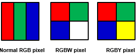
In this case, there is some special design to add one White or Yellow sub-pixel to have RGBW or RGBY pixel structure. Therefore even with full white pattern, backlight dimming with certain percentage could be allowed as the white/yellow sub-pixel will be turned on to compensate on the brightness loss.
The trade-off of this RGBW/RGBY design is on the contrast ratio and color gamut, and color tone on RGBY design. Backlight dimming applied here is mainly for power saving then.
- Resistive Touch and Capacitive Touch, On-cell Touch and In-cell Touch
Resistive touch could be simply understood as a voltage divider.
Let’s take 4-wire resistive touch as an example. Two ITO layers (normally ITO film on top and ITO glass at bottom) are bonded face to face and with air gap. When there is touch, one layer will detect the voltage in x-axis and another layer will detect the voltage in y-axis. Both voltage will help locate the actual touch position.
Capacitive touch has ITO patterns for x-axis and y-axis, either on single layer or different layers. The voltage change caused by the capacitance change on both axis will help locate the touching area.
With LCD technology improvement, LCD manufacturers started to integrate the capacitive touch layer into LCD panel about 10 years back. But there was indeed some argument on the definition on On-cell and In-cell.
Generally, if the ITO layer for touch panel is on color filter glass, it is looked as On-cell touch.
If the ITO layer is on TFT glass, it is defined as In-cell touch.
It is quite straightforward that In-cell touch requires higher technology and process capability, especially on the noise reduction.
- Passive 3D and Active 3D (with Goggles)
The basic understanding on 3D is to have different 2D image in left and right eye, and processed by brain.
Passive 3D panel is to split one frame image into odd lines and even lines. With passive Goggle, left eye can see odd lines and right eye can see even lines. So the drawback of passive 3D is on the resolution loss (by half) on each frame.
Active 3D is to display 3D video with odd frames and even frames. Active Goggle will synchronize with 3D panel/TV and switch on alternatively for left eye to receive odd frames and right eye to receive even frames. So each eye will receive half of the video frames. This is the drawback of active 3D on the spatial resolution loss. Watchers may suffer from the flickering during Goggle On/Off as well.
Author:

Tang Hui
Technical Sales Manager
Sharp Singapore Electronics Corporation Pte Ltd
Published in Telematics Wire