We are currently witnessing a surge in the demand of Lithium-ion batteries for electric vehicles (EVs). As Lithium-ion batteries shares the high proportion of overall EV cost, though it becomes mandatory to make it more efficient and reliable. However, due to highly dynamic nature and high sensitivity of Lithium-ion batteries to operating conditions like temperature, C-rate, and DOD %, it is challenging to keep it in the safe operating areas. Therefore, it is required to understand the functions and topologies of existing Battery Management System as it helps to improve the EV battery performance.
Global EV Market Scenario (2020-2030)
As countries work to reduce carbon emissions, the demand of EVs is increasing. According to IEA, the global and plug-in hybrid EV (PHEV) sales share in 2020 was 4 % and 16 % of total vehicles sale. As demonstrated in Fig 1, by 2030, under the states policies scenario, the EV and PHEV sales will be reached to 16 % and 33%, respectively. Under the sustainable development scenario, EV and PHEV sales will touch 34 % and 31%. Currently, the use of EVs is dominated in the developed like China, USA, France, Japan, Norway, and South Korea. However, this trend is also started to influence many developing countries.

Indian EV market: In developing countries like India, the central and states government drafting the policies to support OEMs and consumers. The global EVs market is expected to reach a value of USD 725.14 billion by FY2026 which will have a major impact on the EV company shares in India, as shown in Fig 2. According to CACR, EV market share in India is expected to increase from USD 5.3 billion (2020) to USD 206 billion by 2030. the demand for EV batteries would create an investment opportunity of USD 17 billion. To meet the goal, demand for EV charging infrastructure would create an investment opportunity of USD 3.2 billion in the EV charging stations market. Under FAME II, around INR 193.57 crores were given out as incentives till FY 2021 by the government.
Why are Lithium-ion Batteries the backbone of EVs?
As we know the Lithium-ion batteries have several prominent features that make it suitable for the use in EV such as high energy/power density, long life cycle, low self-discharge, and no memory effect. Also, their characteristics to support fast charging made it ideal for EV. However, for the safe operation of Lithium-ion batteries it is mandatory to operate it in the safe operating area (SOA). For example, if we operate lithium-ion batteries beyond its temperature range then it would not be possible to charge it completely. Moreover, if we continued to operate outside its temperature limit then the problem of thermal runway may occur and ultimately catch fire. Also, the high depth of discharge (DOD) can easily affect its cycle life. Therefore, to keep the Lithium-ion batteries in the SOA, the electronic chip called battery management system (BMS) is used by the battery manufacturers.
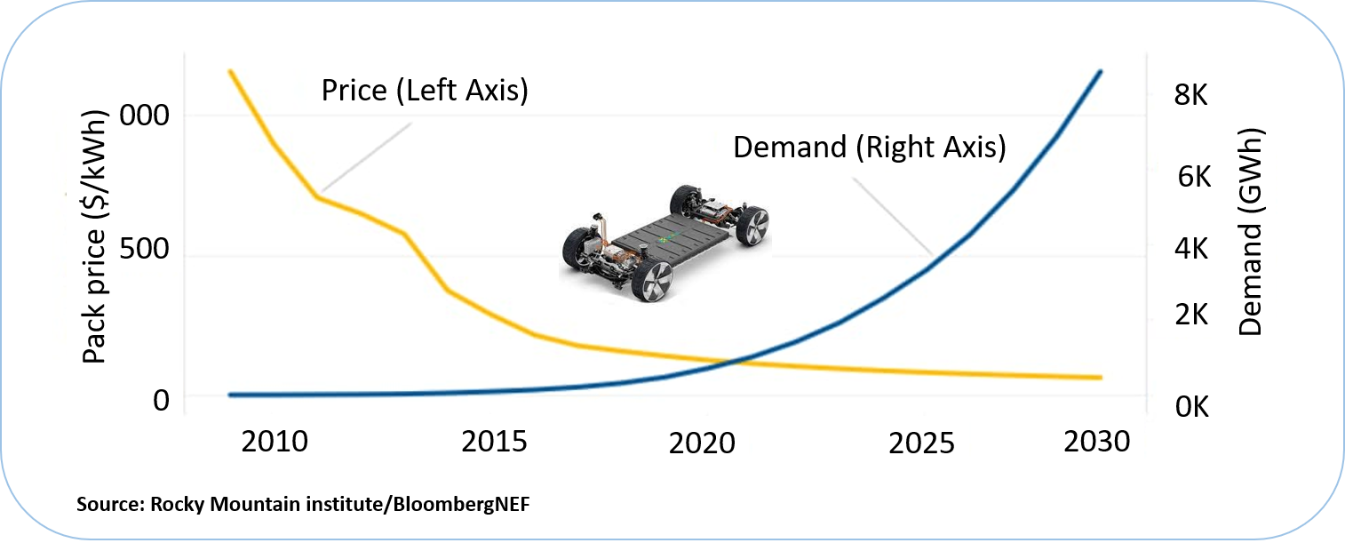
Price and demand of Lithium-ion batteries (2010-2030)
Typically, the prices of the battery pack are measured by the cost per kilowatt-hour. The prices of the battery have fallen over the last 10 years, as the production of battery reached economic scale. According to BloombergNEF, today’s price of battery is $156 per kilowatt-hour, which is around 85% decline in prices from 2010’s which was around $1,100 plus/kWh cost. According to BloombergNEF, the prices of battery will continue to falls, it will reach below $100/kWh by 2024, as the production and efficiency of battery is continuously improving. The cumulative demand for lithium-ion batteries is also increasing, it was just 0.5 gigawatt-hours in 2010, rises to roughly 526-gigawatt hours in 2020. This enormous increase in demand is expected to be continue, which may reaches upto 9,300 gigawatt-hours by 2030, as show in Fig 3. That demand for battery will transform in 10s of millions of energy storage, electrical vehicles, and consumer devices around the world.
Sources of safety hazards in Lithium-ion batteries used in EV
There are different sources of safety hazards in EV batteries during their long life such as manufacturing defects, thermal abuse, electrical abuse, and mechanical abuse as shown in Fig 4. Cell with manufacturing defect caused by the contamination of the chemical is hard to identify after the battery pack development and may trigger the thermal runway. Thus, it is always recommended to adopt rigorous quality control procedure in the battery assembly line. As Lithium-ion batteries is highly sensitive to temperature and rising the temperature beyond the defined limit may trigger the thermal runaway due to undesirable side reactions. Also, the heat generation during thermal stress cannot be controlled. Mechanical stress commonly occurs during accident and it may cause due to many reasons such as compression, punching and twisting of cells connected the battery pack and damage of shell casing. The electrical abuses that commonly occurs in the EV batteries are due to malfunctioning of the protection circuitry and mishandling are:
- over-voltage
- overcharge
- over-current
- external short circuit
- charging outside of the accepted
- over-discharge, and fast charging of over-discharged cells
- deep discharging
If the EV battery remains in the electrical abuse condition for longer/multiple time, it will increase the thickness of SEI layer and form the dendrite on the surface of electrodes. Due to SEI layer thickness increment, the internal resistance of the battery will increase. Other side, with the formation of dendrites, the separator can be punctured, and internal short circuit will occur. The mechanical, electrical, and thermal abuses are the main cause of triggering of thermal runaway and fire of EV batteries. However, With the use of BMS EV batteries can be protected from the thermal runaway to some extent.

The functionality of BMS and existing topologies
BMS is an electronic system that serves as the brain of the battery system. As shown in Fig 5, some of the key functions of BMS are charge and discharge control, thermal management system, cell monitoring, and balancing, fault diagnosis and health management, data acquisition, and modeling and state monitoring. The economic advantages of BMS are extensions of battery lifetime and lowering the cost. For example, BMS shares only 8% of the total battery pack cost for a 22 kWh mid-size EV battery pack. Standardization of BMS for EVs and proper implementation of the standards in EVs can reduce risks and hazards associated with BMS significantly.

Data Acquisition: The data acquisition includes the monitoring and storing of the most relevant battery data for decision-making units of BMS. The most relevant battery data are the measured voltage of every battery-connected battery cells, the current flows in parallel connected modules in the battery pack, and the temperature of each battery cells. The proper sampling frequency of voltage and current measurement is always required to capture the transient response of the battery cells.
Thermal management system: LIBs are very sensitive to temperature. The increase in temperature has two effects on the performance of Lithium-ion batteries. With the increase in temperature, the Lithium-ion battery’s performance improves and works more efficiently. Therefore, to maintain the temperature within the safe operating temperature range, the thermal management system is generally equipped with a battery pack.
Safety and Protection: To protect the battery cells or battery pack from malfunctioning and permanent damage, different sensors are incorporated with BMS. With the help of sensor signals, the battery cells can be protected from overcharge, undercharge, insulation fault, uniformity fault, over-fast temperature rise, and low temperature. When the faults are diagnosed, the sensor signals are transmitted to the vehicle control unit to handle the faults. Under a serious fault condition, the vehicle control unit disconnects the battery pack from the power supply also.
Charge and discharge control: All batteries have limited numbers of charge and discharge cycles, so this function of battery should be properly managed for better life backup. Along with this, the most harmful thing that can happen to the battery is overcharging.
Cell Balancing: Due to inconsistency among the battery cells, the small imbalance in voltages of the battery cells is always present. Due to imbalance in voltage, overcharging and deep discharge case may be occur in few cells. This also impact the performance, operation, and safety of battery pack. To outperform this, the cell balancing circuit is available in BMS. Generally, there are two types of cell balancing methods are used in BMS such as active cell balancing and passive cell balancing. Passive cell balancing is also known as dissipative cell balancers and active cell balancers as non-dissipative cell balancers.
Battery States monitoring: For development of robust and efficient BMS, various battery states need to monitor accurately such as State of Charge (SOC), State of Health (SOH), State of Power (SOP) and State of Energy (SOE). However, these states of battery cannot be measured directly through any electrical instruments. Therefore, these states are estimated through various methods using measureable quantities of batteries such as battery terminal voltage, current and operating temperature.
BMS Topologies:
Selection of suitable topology in large size BMS is very crucial task to optimize the cost. BMS topology defines the connections between the individual cells to monitor, control structure and communication architecture. The BMS topologies can be classified into three categories as Centralized, Distributed, and Modularized or Master-Slave, as shown in Fig 6. Further, the properties of different properties are listed in Fig 7.

Centralized BMS Topology: One master controller is monitoring each cell and control the overall functioning of battery pack.
Distributed BMS Topology: All the cells have its BMS that sends signals to Master controller to control the functioning of battery pack.
Modularized BMS Topology: Different identical slave module BMS connected with individual batteries or battery cells for monitoring and controlling. In which, one of the modules BMS serves as Master BMS and control the overall functioning battery pack based on the signals send by the slave BMS.

Selection criteria for right BMS
- Compatible with desired battery chemistry: As the characteristics of different chemistry batteries vary greatly from each other. Hence, the BMS must support the desired chemistry according to the battery pack.
- Number of series cells: BMS must have the feature to support the maximum number of cells in series available in a battery pack.
- Max. Current and Voltage Rating: Selected BMS current and voltage rating must be slightly higher than the continuous current rating and maximum voltage so that it doesn’t struggle from the demand of the controller, respectively.
- Max. Balancing Current: Large balancing current results in less time required for balancing of battery pack but it may also cause thermal problems if thermal management is not well supported.
- Estimated SOC accuracy: Better SOC accuracy results in less drifting of SOC, if BMS have less SOC drift from actual SOC, prevents battery from deep discharge or overcharge conditions.
- Sensor’s accuracy: Selected BMS must have a better sensor rating for better measurement of temperature, voltages, and current values which are also used in SOC estimation of battery.
- Communication method: CAN 2.0 is necessary for the automobile domain, BMS must be able to support UART communication for wireless peripherals such as Bluetooth, wifi, or an IoT device, according to customer requirements.
- Maximum channel per slave: Depending on the battery pack voltage range, the requirement of the voltage channels per slave generally varies.
- Programmable input and output: Programmable input and output pins result in large numbers of application or safety-related parameters for BMS such as ignition signals, low charge signals, external wakeups signal, etc. Higher the number of programmable pins the better the application of BMS.
What should be in the Next-generation BMS?

Next-generation BMS should be different from traditional BMS in different aspects to improve the life cycle and performance of EV Lithium-ion batteries. Some of the features of next-generation BMS are:
- It should have the capability to celebrate with real-time data instead of laboratory data.
- It should be capable to work with a 5G high-speed information system and bandwidth so that the advantages of big data and cloud computing will be fully utilized. So, the limitations of computation power ad storage capacity in traditional BMS will be reduced significantly.
- It should have the feature to adjust the degree and rate of charge based on health especially during fast charging.
- In the next generation BMS, the concept of digital twin should be utilized to improve the data logging.
- With the application of an advanced co-estimation algorithm for SOX (SOC, SOH, SOP, and SOE) estimation in next-generation BMS more reliable and cost-effective Lithium-ion battery pack will be developed.
Authors:

Dr. Prashant Shrivastava
Sr. Research Engineer
Emuron Technologies Pvt Ltd
Prashant Shrivastava brings more than 4 years research expertise on battery modeling and states estimation, battery testing and EV charging infrastructure development to his role of senior research engineer at Emuron Technologies Pvt Ltd. He holds his PhD from University of Malaya, Malaysia and M. Tech from Aligarh Muslim University, Aligarh (India). He has authored and coauthored in decent number of research articles published in reputed journals, and international conferences.

Robin Kumar
Embedded System Engineer II
Emuron Technologies Pvt Ltd
Robin Kumar has been working on embedded Systems since his college days and have keen interest in designing of electronic, embedded system, electronic vehicle. He has competed with various FSAE team allover world in the past. He hold his B.tech from IIT Delhi. He is currently associated with Emuron Technologies, working on developing new technologies for EV in India.
Published in Telematics Wire