Electric Vehicle Driving Range limitation is a primary roadblock to public acceptance of Electric Vehicles. Currently, the maximum driving range of production worthy Electric Vehicles is 400 miles (The Tesla Model Y). The Driving Range of conventional ICE (Internal Combustion Engines) with a 22 gallon tank ranges from 550 Miles to over 2000 Miles. Obviously, much needs to be done to improve EV Driving Range.
As EV battery capacity, alternative energy sources, and EV motor efficiency increases are on the horizon, however, putting these lab innovations into production and practice at an economical cost is not yet realized.
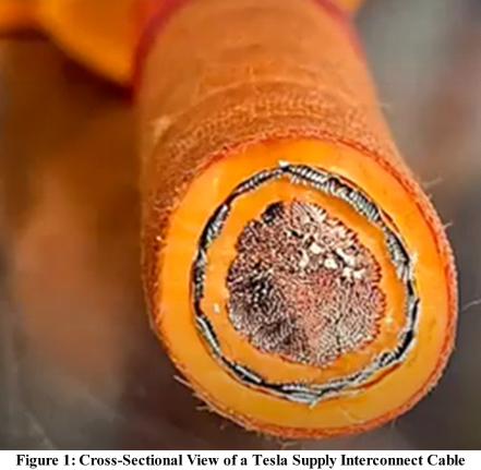
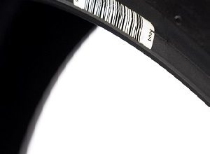
There is much noise energy in Electric Vehicles today, generated by the Vehicle Traction Inverter, so much so, that Tesla uses what are in essence Coaxial Cables in their vehicles for electrical interconnect. See the cross-sectional view in Figure 1.
This cabling is done to prevent the EV from being a “transmitter’ of noise generated energy as the outer shield is grounded to the chassis of the EV. If this noise can be captured, re-purposed, and re-used, needed battery current can be reduced in the EV system, and EV Driving Range Mileage increased.
The NEW Technology
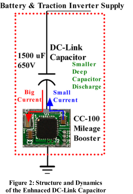
CurrentRF has developed IC technology that captures, re-purposes, and re-uses this afore mentioned noise current. Figure 2 shows the basic function of this technology. All Electric Vehicles have a “smoothing capacitor” or DC-Link Capacitor that filters and shunts Traction Inverter generated noise away from the Traction Inverter-Battery supply line to system ground. This is done to increase Traction Inverter efficiency. This filtering is not perfect and the noise the DC-link Capacitor shunts to ground draws battery current during the re-charge cycle of the Capacitor.
CurrentRF has developed an IC that attaches to the ground side of a DC-Link capacitor, absorbs this DC-Link Capacitor ground current, inverts a portion of this current, and outputs this current in opposite phase, cancelling a portion of the original current impulse. This action limits the “deep-discharge” of the DC-Link Capacitor, limits the supply line noise, decreases the current drawn from EV system batteries, this said current needed to re-charge the DC-Link Capacitor.
This current reduction ultimately extends the Driving Range of a given Electric Vehicle.
The Installation, Versions, and Testing
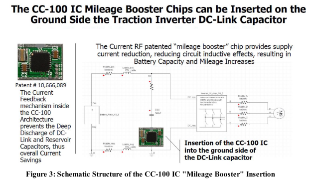
Figure 3 shows the internal insertion of the CC-100 IC into the DC-Link Capacitor and Traction Inverter Electric Vehicle Drive Train. As shown, the CC-100 IC fits directly underneath, on the ground side of the system DC-Link Capacitor preventing the deep discharge of the DC-Link Capacitor, lessening the recharge current drawn from system batteries, ultimately extending Electric Vehicle Driving Range
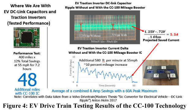
The primary challenge to Electric Vehicle public acceptance is Vehicle Driving Range. Figure 4 shows the testing results obtained from an Electric Vehicle Drive Train. With the testing results shown in Figure 4, the battery current saved and the resulting mileage extension of an Electric Vehicle Drive Train is obtained as the result of using the CC-100 technology attached to the ground side of a typical Electric Vehicle DC-link Capacitor running in an Electric Vehicle Drive Train. The physics and dynamics of the CC-100 technology allows the “Enhanced DC-Link Capacitor” to be placed at any point in the Traction Inverter and EV Battery supply line, and
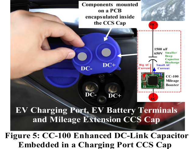
even at the DC charging ports of an Electric Vehicle as shown in Figure 5 (consumer version).
The cost of this solution is $39.00 per Electric Vehicle (minimal as compared to the Electric Vehicle cost), is available today and needs to be implemented in any of the commercial forms shown in Figures 3 and 5. The implementation of this technology will yield an additional 10% in Driving Range, or 50 miles of Driving Range, given a Tesla model Y nominal Driving Range of 400 miles on a single battery charge. As battery technology and motor technology advance, giving the Electric Vehicle increased Driving Range, the Driving Range increases as the result of the CC-100 technology will increase as well. In essence, the longer the battery stays up, the larger the CC-100 Enhanced DC-Link Capacitor induced Driving Range increases will become. The CC-100 technology is obsolete-proof.
EV Current Reduction, Noise Reduction, and Mileage Extension Testing
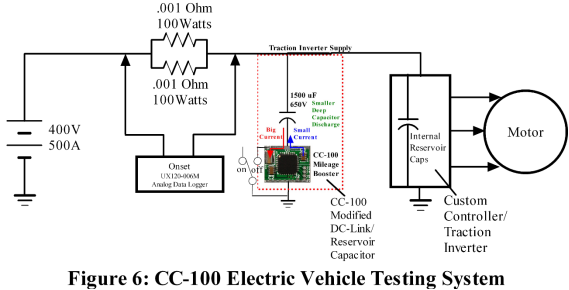
In that the Traction Inverter noise contained on battery supply lines in Electric Vehicles is difficult to measure and quantify, CurrentRF has developed testing procedures and an architecture that allows current measurements and reveals the delta in battery current with and without the CC-100 engaged, as shown in Figure 4. The schematics of this testing architecture are shown in Figure 6.
Testing Procedures
The procedure for this noise and current reduction measurement is simple. First, control the torque to which the Electric Vehicle Drive Train is mechanically exposed.
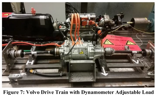
This is done with the use of a controlled incline dynamometer shown in Figure 7. Secondly, with the torque control set-up, control the speed of the vehicle and the incline emulated torque that the dynamometer applies to the Electric Vehicle. Thirdly, with these controlled mechanical conditions set, test the Electric Vehicle with and without the CC-100 Enhanced DC-Link Capacitor engaged. This testing should be done “back to back” (i.e. one test run with the CC-100 Enhanced DC-Link Cap disengaged, the follow on test run with the CC-100 Enhanced DC-Link Capacitor engaged). This “back to back” controlled testing should be done with equal mechanical, vehicle speed, and test time duration conditions. For each of these tests, the voltage drop across in series sense resistors (series resistors from the battery pack to Traction Inverter and DC-Link Capacitor) shown in Figure 6, is recorded with an Onset UX120-006M Analog Data Logger also shown in Figure 6. Fourth, after this data is recorded, it can be downloaded into a spreadsheet and using Ohms Law, the with and without battery currents can be computed and subtracted, creating the delta plot shown in Figure 4.
Conclusions
Clearly, EV System “noise loss” is a phenomenon that is not understood by most in the Electric Vehicle Industry. This non-understanding is exasperated by not being able to directly test for this noise or do anything about this “noise loss” in battery current draw. The CC-100 IC is the only device on the market today that can capture, re-purpose, and re-use the noise present in Electric Vehicle Drive Trains, the CC-100 IC creating the CC-100 Enhanced DC-Link Capacitor. This simple 2-wire connected device is economical and is easy to build and install in new and existing Electric Vehicles. CurrentRF can provide sample devices and assist in the testing of these devices in Electric Vehicle Systems.

8656 Fresno Circle
Huntington Beach, Ca.
92646
Michael.Hopkins@CurrentRF.com
www.CurrentRF.com
(209)-914-2305
Author
Michael Hopkins
Founder and CEO
CurrentRF
Michael Hopkins is the Founder and CEO of CurrentRF, A California based research and development company, founded in 2002. Through activities with CurrentRF, Michael developed the RFDAC methodology and Current Reuse Mixer (the CRF2101) in 2002, and more recently, the CC-100 IC and Enhanced DC-Link Capacitor technologies (subsystems, chips, IP) the company is currently marketing.
Published in Telematics Wire